


Did you know that electric vehicles actually predate gasoline-powered cars? While there’s some debate about whether the first electric vehicle was invented in 1832 or 1881, it’s clear that it came before Karl Benz introduced the first gasoline-powered car in 1886. In fact, electric and gasoline cars were neck and neck in popularity around the early 1900s. However, the rise of the petroleum industry in the 1920s made gasoline significantly cheaper, and the internal combustion engine has dominated the automotive industry ever since. Electric vehicles became a mere footnote in automotive history.
The Importance of BMS
Despite this, electricity remains a crucial component of modern vehicles. In electric vehicles, power management is even more critical. If the battery is the heart of an electric vehicle, then the Battery Management System (BMS) is its brain. The BMS controls and monitors the electric vehicle’s power, ensuring optimal battery performance, longevity, efficiency, and most importantly, safety. It monitors the battery system to prevent issues like overcharging, over-discharging, and short circuits.
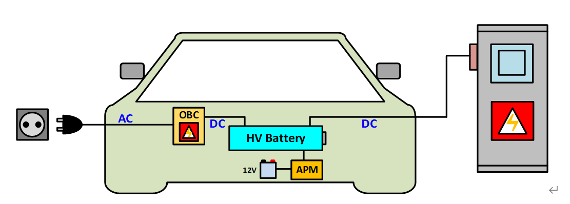
An electric vehicle’s power comes from a high-voltage lithium-ion battery pack composed of numerous cells connected in series and parallel. This battery can be charged directly using a DC fast charger or indirectly using an AC charger and the vehicle’s on-board charger (OBC), which converts AC power to DC power. The high-voltage battery can directly power high-voltage components like the motor inverter or air conditioning inverter, or it can be converted to 12V by an auxiliary power module (APM) to power lower-voltage components like the vehicle’s computer, lights, and wipers.
To protect the high-voltage battery from damage, the BMS, which includes components like transient voltage suppressors (TVS) and diodes, manages charging and discharging, selects power sources, and monitors and protects the battery system.
BMS Architecture
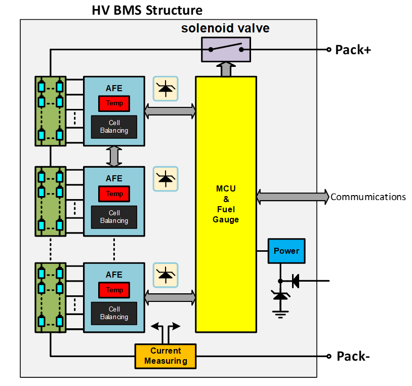
Typically, a BMS consists of a control module and a measurement module: an analog front-end (AFE), a microcontroller unit (MCU), and a gauge (see figure). The gauge can be a separate IC or integrated within the MCU.
The AFE’s function is to balance the energy of individual lithium-ion cells and provide voltage, temperature, and current readings from the battery to the MCU and gauge. The gauge obtains readings from the AFE and then uses complex battery modeling and advanced algorithms to estimate critical parameters such as State of Charge (SoC) and State of Health (SoH).
The MCU is the core component of the BMS. It connects to the system and receives information from the AFE and gauge. As the BMS needs to prevent the vehicle’s battery from overheating due to overcharge or over-discharge, leading to fire or explosion, the MCU will quickly transmit a signal to the relay when there is an anomaly, controlling whether the current in the entire circuit is working normally or is cut off.
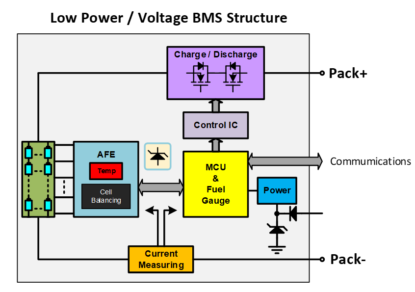
For low-voltage BMS architectures in applications like electric motorcycles and golf carts, where system currents are relatively low, the relay structure is often replaced with a back-to-back N-channel MOSFET configuration for charge and discharge protection. To minimize power losses in the circuit during operation, MOSFETs with low on-resistance (RDS(on)) are selected to protect the battery while achieving low power dissipation and improving circuit conversion efficiency, ensuring stable power supply.
The AFE module’s operating power typically comes from the managed lithium-ion battery. Due to occasional transient voltage spikes on the lithium-ion battery line, a TVS (Transient Voltage Suppressor) is added to both the control circuit and the lithium-ion cell to prevent damage to the control circuit. When a transient voltage occurs, the excess energy is dissipated through the TVS, protecting the acquisition module.
The power supply for the MCU and gauge modules primarily comes from the vehicle’s 12V battery. A TVS and a reverse protection diode are added to the front end of the power supply to meet safety regulations.
Taiwan Semiconductor offers a comprehensive range of components, including TVS, Zener diodes, and MOSFETs, to support your BMS and ensure optimal vehicle power management.
Products
Read more articles
- The Role of MOSFETs in Anti-lock Braking Systems (ABS)
- Beyond Braking: Advanced Driver Assistance Systems (ADAS) for a Safer Driving Experience
- Powering the Electric Revolution: The Body Control Module (BCM) in Automotive
- Advanced LED Solutions for Enhanced Vehicle Visibility
- Power Components for On-Board Chargers (OBC): A Comprehensive Overview
- MOSFETs and Diodes: Key Components in Reverse Polarity Protection
- Sensor Fusion for Supplementary Restraint Systems (SRS)